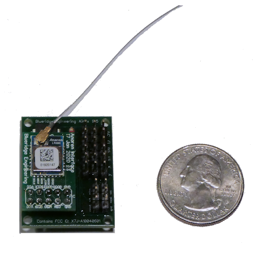
Airwire Receiver The AirRx is a small board that allows you to control Large Scale locomotives using battery power and Airwire Transmitters. It can operate in several modes- DCC, ESC, PWM and Servo. $59
|
General Description
The AirRx is a Airwire Compatible Receiver for dead rail. This is a high efficiency long range 915Mhz receiver that uses the Anaren Chipset. Like the Protothrottle Receiver, it can be programmed to operate in one of four modes- Battery DCC, Electronic Speed Control, PWM and Live Steam. The AirRx is a bit different than the PTRx in that it is two DCC devices in one package. As an Airwire Receiver, it sets up the radio and then passes the DCC signal from the Airwire Transmitter directly to the ‘D’ pin on the receiver. You then hook the Cytron Power Amp to that for 10Amps of DCC.
While the DCC signal is passed to the output pin, it is also intercepted and decoded inside the Receiver to control the outputs for the ESC, PWM and Live Steam (servo) modes.
DCC Output Mode
Below is a block diagram of the components when used in DCC mode.
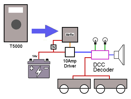
The AirRx intercepts the T5000 signal and outputs it as logic level DCC. That signal is then used to control a motor driver which effectively ‘boosts’ it up to whatever voltage your battery is (typically 14-18v). The 3v supply shown is a small ‘buck’ converter that draws power from the main battery to produces a clean, steady 3v to power the receiver. The Motor driver (Amp) outputs then directly drive the DCC decoder.
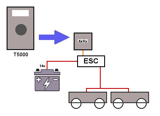
ESC Output Mode
The hookup for the ESC mode is similar, however in this case we are using the Servo 0 R/C output signal. Below is a block diagram. Here we are using the BEC circuit to power the receiver so we don’t need the 3v converter. (make sure that the BEC outputs 3v, otherwise you will have to convert the battery power to 3v as shown in the DCC diagram above).
Most Electronic Speed Controls have an R/C input and this is (almost always) a ‘center-off’ input. An R/C pulse is always between 1000 and 2000 micro seconds. The center off mode sets the pulse to exactly in the middle of that range (1500us) to stop the motor. As the throttle is advanced, the pulse width increases until it gets to 2000us which is full speed forward. Likewise, when the knob is depressed on the T5000 for reverse, advancing the throttle then decreases the pulse width from 1500 until it gets to 1000 which is full speed reverse.
Note the relay outputs. The AirRx has two digital outputs that can be assigned to DCC Function Codes to drive relays or other outputs. Pololu Relay Module
You can set the parameters in the AirRx using CV codes sent by the T5000 Airwire Throttle.
/*
 * CV Map for AirRx
 *
 *   CV 201 - Radio Channel 0-15
 *   CV 202 - DCC Address lo
 *   CV 203 - DCC Address hi
 *   CV 204 - Servo Mode 0=Steam, 1=couplers, 2=ESC, 3=PWM
 *   CV 205 - Servo0 LowLimit Lo
 *   CV 206 - Servo0 LowLimit Hi
 *   CV 207 - Servo0 HighLimit Lo
 *   CV 208 - Servo0 HighLimit Hi
 *   CV 209 - Servo0 Reverse
 *   CV 210 - Servo1 LowLimit Lo
 *   CV 211 - Servo1 LowLimit Hi
 *   CV 212 - Servo1 HighLimit Lo
 *   CV 213 - Servo1 HighLimit Hi
 *   CV 214 - Servo1 Reverse
 *   CV 215 - Function Code for Coupler 0
 *   CV 216 - Function Code for Coupler 1
 *   CV 217 - Function Code for Output x
 *   CV 218 - Function Code for Output y
 *   CV 219 - On/Off Code for Output x
 *   CV 220 - On/Off Code for Output y
 *   CV 230 - Reset to factory defaults
 */
Connectors Description
Below is a diagram of the pins on the Receiver. These are standard R/C connections, the pins closest to the edge of the board are ground, the pins in the middle are +3v and the pins nearest the chip are the signal pins.
Note that this is a THREE volt device, do not hook 5v to it for any length of time!
   Y   X  s1  s0   D   3v
   |   |   |   |   |   |________ Power Connection (+3v)
   |   |   |   |   |____________ DCC logic level out
   |   |   |   |________________ Servo 0 (Throttle)
   |   |   |____________________ Servo 1 (Direction in Steam mode)
   |   |________________________ Digital Output X
   |____________________________ Digital Output Y
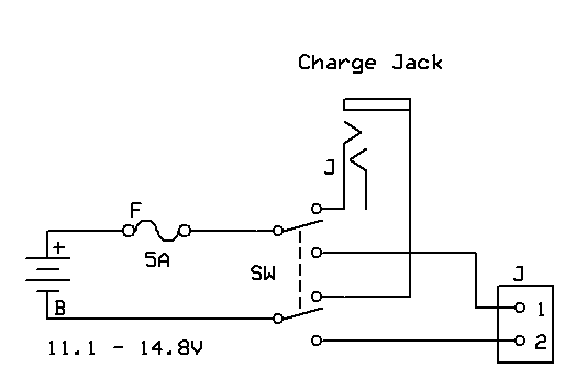
Power Connections
The schematic below shows how I wire all my installations. A DPDT switch is used to connect the battery to either the charge jack or power the system. This makes a nice clean break of all power to the system. DO NOT forget a fuse! If you use Lipo batteries, they can dump a TON of current if they are shorted and with no fuse it will melt wires and cause all sorts of havoc if you make a mistake and short them.