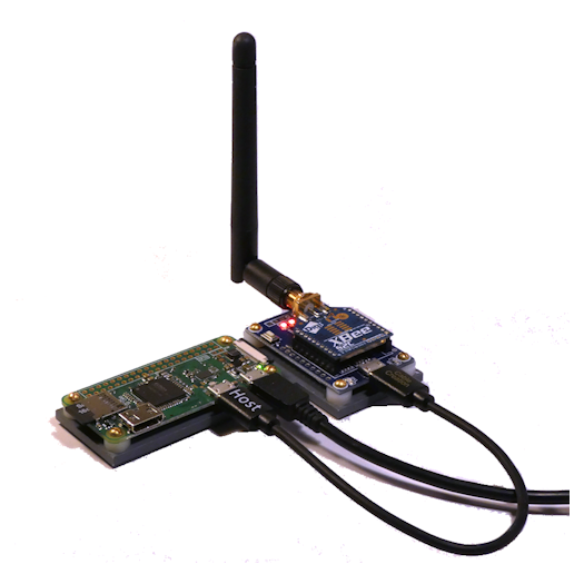
Xbee Network ProgrammerThe Xbee Programmer allows you to program your Protothrottle Receivers. These are based on the Raspberry Pi with a USB connection to an Xbee. The Rpi is configured as a standalone wifi access point with it’s own web server. Use your computer or tablet to connect to the programmer through a browser and from there you can query the xbee network and program all of your Receivers. $99
|
Setup and Connecting
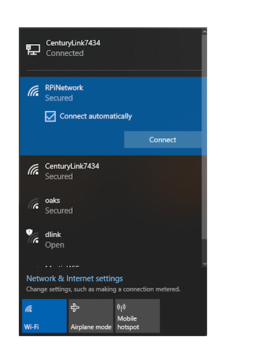
The programmer doesn’t really need any setup, just power it up and let it sit while it initializes. Once it’s up and running, connecting to it depends on the device. The Programmer is a web server with a built in Wifi access point, so the basics are the same for all devices. Find the wifi network ‘rpinetwork’ and connect. It will ask you for a password, it is ‘mypassphrase’ without the quotes.
To the left is an image of a Windows 10 machine showing the connection button. Once connected, use a browser such as Netscape or Chrome to connect to the programmer. |
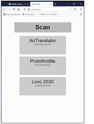
This is the main screen. This shows a network with the Protothrottle, a locomotive receiver and the AirwireTranslator. In this instance, I have set the name of the Protothrottle to ‘Protothrottle’. From the factory, the Xbee in the PT does not have a Node ID, so this will be blank with your PT (however, you can set it with this app if you wish)
Note the rpinetwork in the browser URL bar and the big scan button. When you click scan, an Xbee Network Query is sent from the programmer and all Xbees in range will respond. The programmer takes those and populates this screen. You may have to click the scan button more than once and wait a bit of time in between as the Xbees sometimes are a bit slow to get all of the network IDs back to the programmer. |
|
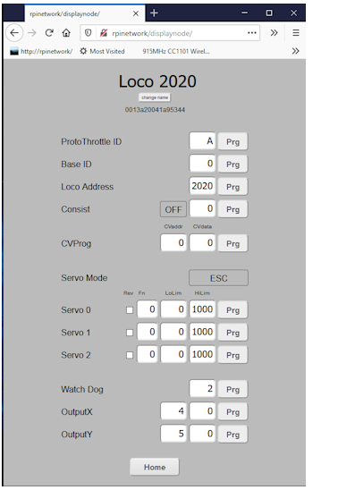
In this image, we have clicked on the Loco 2020 button to ‘zoom’ into the receiver configuration. Here is a description of each of the parameters:
|
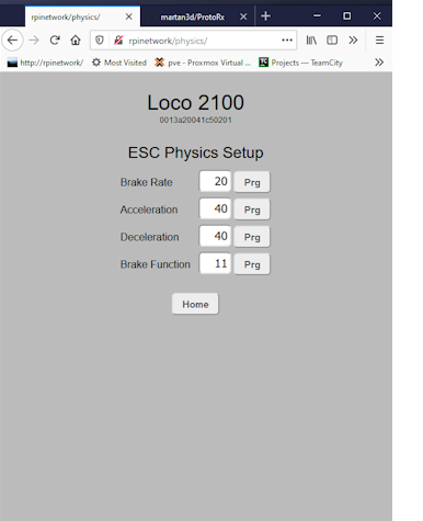
PHYSICS parameters. These affect the ESC output and only if PHYSICS mode is selected. These parameters allow you to use an Electronic Speed Controller and simulate acceleration, deceleration and braking. With the exception of the brake function code, each of the parameters are in milliseconds.
For example, if you have the acceleration set to 40 and move the Protothrottle throttle lever to notch 3, (which is an actual throttle value of 39 out of 128), then every 40 milliseconds the actual output throttle value will increment by one until it reaches 39. For the braking function, the Brake Function parameter gives the function code that you assign to the the PT brake. In the options menu of the PT, the variable brake must be set to on and the mode set to ‘pulse’ with a value of 0.2s. As you move the brake lever to more brake, the brake value in the receiver increments and that is then applied to the throttle value at the brake rate (in milliseconds) in the opposite direction. |
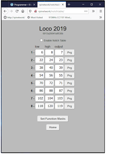
If the consist function is enabled, a button will be displayed at the bottom of the configuration screen above – ‘Notch Table’. This allows you to more closely match notch settings with speeds. The notch values are the throttle values between 0 and 128. They are pre-set to the Protothrottle default values. When a throttle value comes in, it is checked against each notch. If the value is higher than the low setting and lower than the high setting, the receiver will set the dcc throttle value to the output value. By setting the output value you can have your consisted locomotive go slower or faster than the master in order to adjust for variations in makes, motors and different decoders.
|
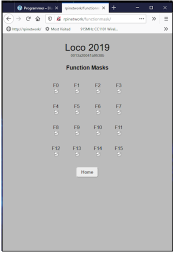
The last screen for consisting is the function mask screen. If you won’t want all of your slave locomotives to respond to function codes, for example the bell and horn, you can mask them off here. Each code from zero through fifteen can be enabled or disabled. A checkmark enables, blank disables.
|
Upgrading the Programmer
Download the image and burn it onto an 32G SSD card. You can get it here http://blueridgeengineering.net/bin/
rpiweb25.zip