Protothrottle Receiver
Theory of Operation
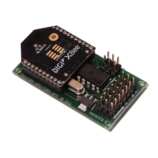
The Protothrottle uses an off-the-shelf wireless communications device called the Xbee. Unlike Airwire or other R/C designs, the Xbee is closer to an internet sort of communications network. There are broadcast and directed messages that can be formulated and sent in a defined protocol. The Xbee is an industrial strength solution and is available in two main types, the standard and the Pro. The standard type has a range of about 100 meters (400ft) outside and the Pro can do about twice that. A good comparison and guide can be found on the Sparkfun Xbee Page
The PT sends out a broadcast message to all Xbees on the network once per second. However, if a control is changed, a message is sent immediately. This message contains all of the information needed to construct a DCC stream or drive an Electronic Speed Control or Servo. Every packet has the locomotive address, the throttle value and a bit for each of the function codes 0-28.
The receiver examines each of these broadcast messages from the PT. If the locomotive, PT and base address match, the message is passed to the DCC/ESC/Servo generation code inside the receiver. The receiver uses this info to format a DCC output stream and set the proper timing for the R/C outputs.
In all modes, Servo 0 follows the DCC throttle dependent on the servo mode setting. In ‘ESC’ mode, servo output 0 is combined with the direction to produce a ‘center-off’ signal compatible with Electronic Speed Controllers. In ‘Steam mode’ Servo 0 follows the throttle directly and instead of a ‘center-off’ signal, the direction is used to control servo 1. It is set to the low limit or high limit depending on the direction setting from the PT.
Configuration
The receiver comes pre-configured and can be used ‘out of the box’ with no programming. As mentioned above, the receiver outputs both DCC and ESC signals simultaneously. The ESC always follows the DCC throttle so they are (more or less) in sync. If you use an ESC to control a larger motor, you can also use a DCC decoder for the sounds if you wish.
However, if you want to change the default parameters of the Receiver, you will need the programmer. For a list of programmable parameters in the Receiver, check out the Programmer documentation This also shows the default values that are programmed in the receiver when we ship it (with the exception of the PT locomotive address which is printed on the documentation included with the receiver.)
DCC Output Mode
Below is a block diagram of the components when used in DCC mode.
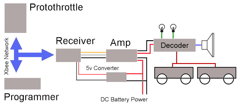
The Receiver intercepts the Xbee broadcast packets sent by the PT. It uses this info to generate the proper DCC stream which is output on the ‘D’ pin. This is fully NMRA compliant DCC, however it is only at a logic level (5v). That signal is then used to control a motor driver which effectively ‘boosts’ it up to whatever voltage your battery is (typically 14-18v). The 5v supply for the receiver is a small converter that draws power from the main battery and steps it down to 5v. The Motor driver (Amp) outputs then directly drive the DCC decoder. (Note that the Programmer is shown in this diagram, however it is not required for the operation of the Receiver)
Standard DCC hookup using the Soundtraxx TSU-4400
ESC Output Mode
The hookup for the ESC mode is similar, however in this case we are using the Servo 0 R/C output signal. Below is a block diagram. Here we are using the BEC circuit to power the receiver so we don’t need the 5v converter. Some ESCs have a decent BEC, others do not. It also depends on if you are going to drive servos as these take more current depending on their size. Generally unless it’s a smaller model, it’s a good idea to use a separate 5v supply, Pololu.com has a great selection of 5v step-down devices.
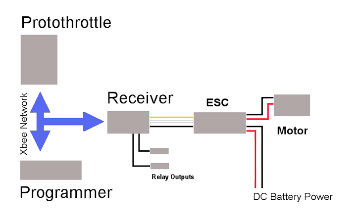
Most Electronic Speed Controls have an R/C input and this is (almost always) a ‘center-off’ input. An R/C pulse is always between 1000 and 2000 micro seconds. The center off mode sets the pulse to exactly in the middle of that range (1500us) to stop the motor. As the throttle is advanced, the pulse width increases until it gets to 2000us which is full speed forward. Likewise, when the reverse lever is set on the PT, advancing the throttle then decreases the pulse width from 1500 until it gets to 1000 which is full speed reverse.
Note the relay outputs. The PTRx has two digital outputs that can be assigned to DCC Function Codes from the PT to drive various outputs but note that these are 5v logic signals so to drive any sort of large load you will need a mosfet type of circuit.
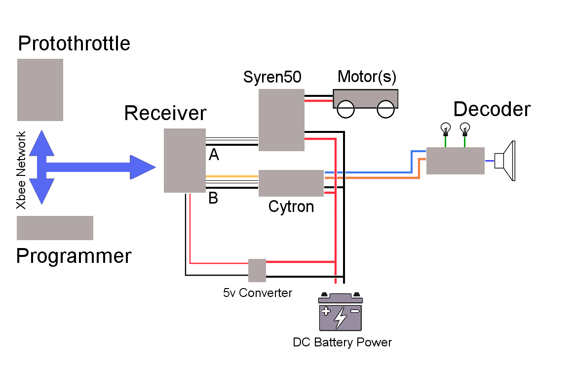
Hybrid Output Mode
For those that want to drive larger motors, this is the hybrid setup I’ve been working with. Basically, the DCC decoder drives the Sounds and Lights while the Syren50 high Amp Motor Controller drives the power trucks. In the figure below, A is the servo 0 output of the Receiver. Note that it is only two wires, ground and the signal. With the Syren50, the BEC (battery elimination circuit) is not adequate to drive the Receiver so we don’t need the 5v, just the signal and ground. The connection marked ‘B’ in the diagram is the DCC output (D pin) of the receiver. This is a logic level signal so we are using the Cytron to rapidly switch the large voltage to produce full DCC which drives the decoder.
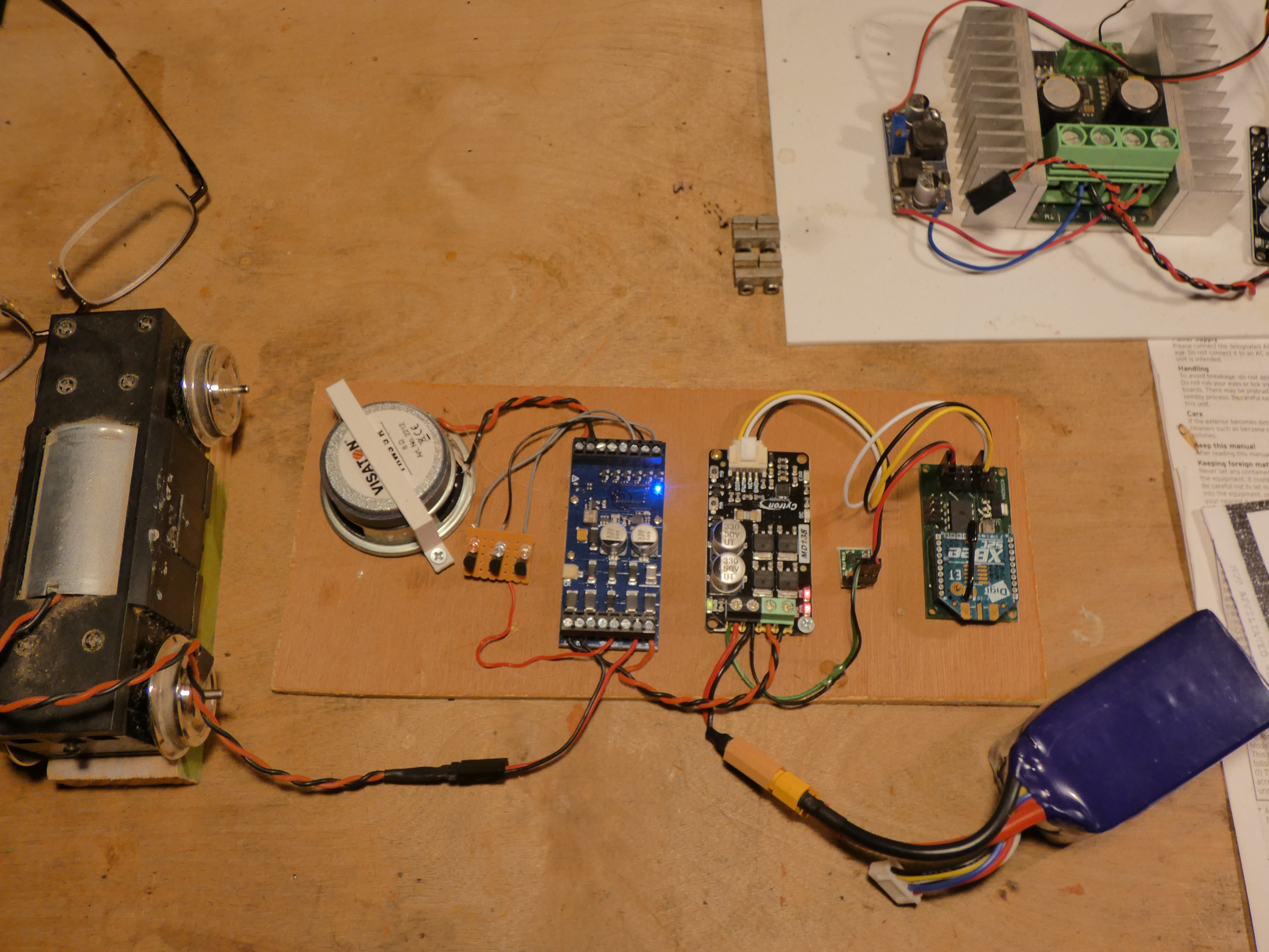
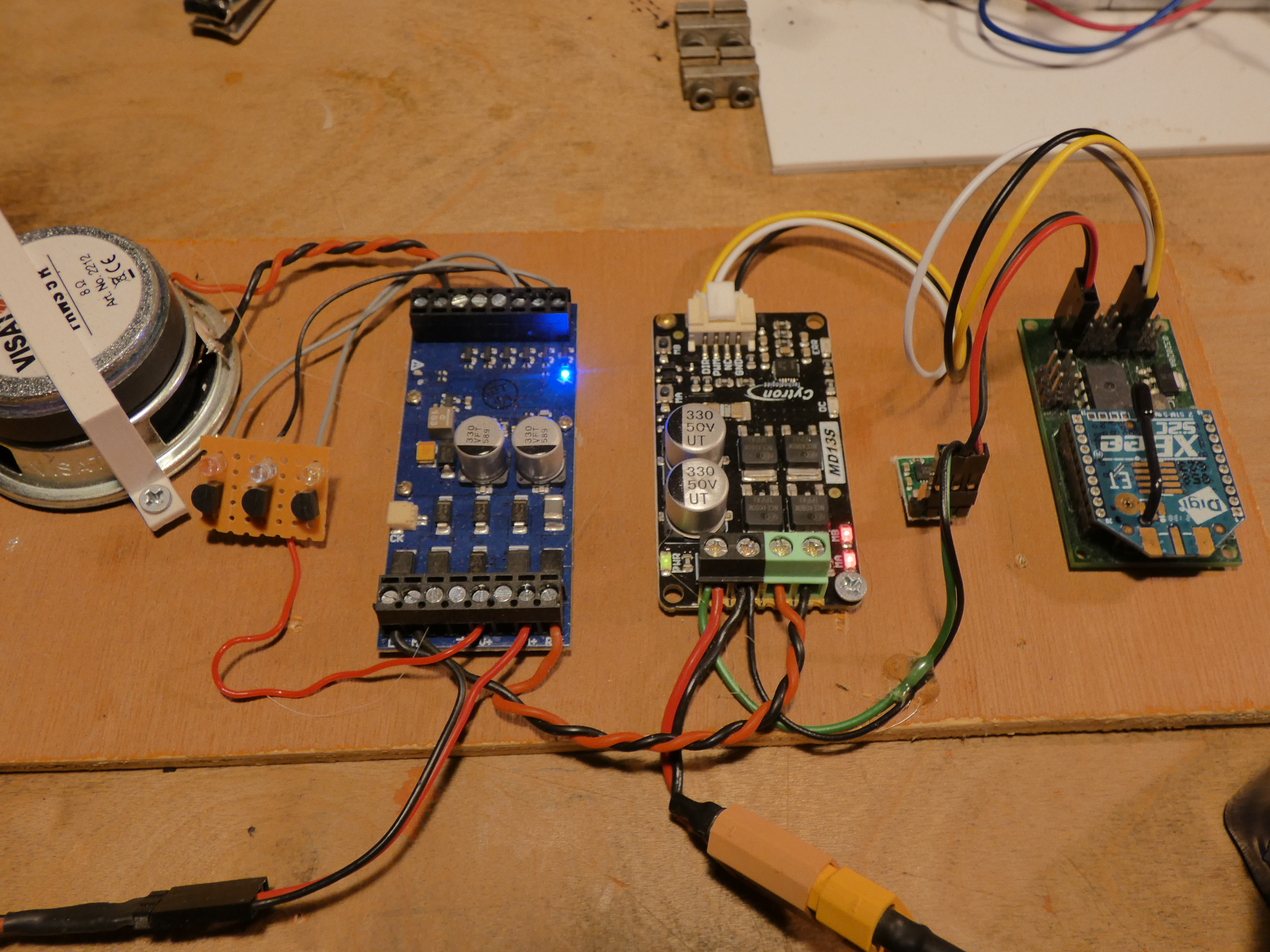
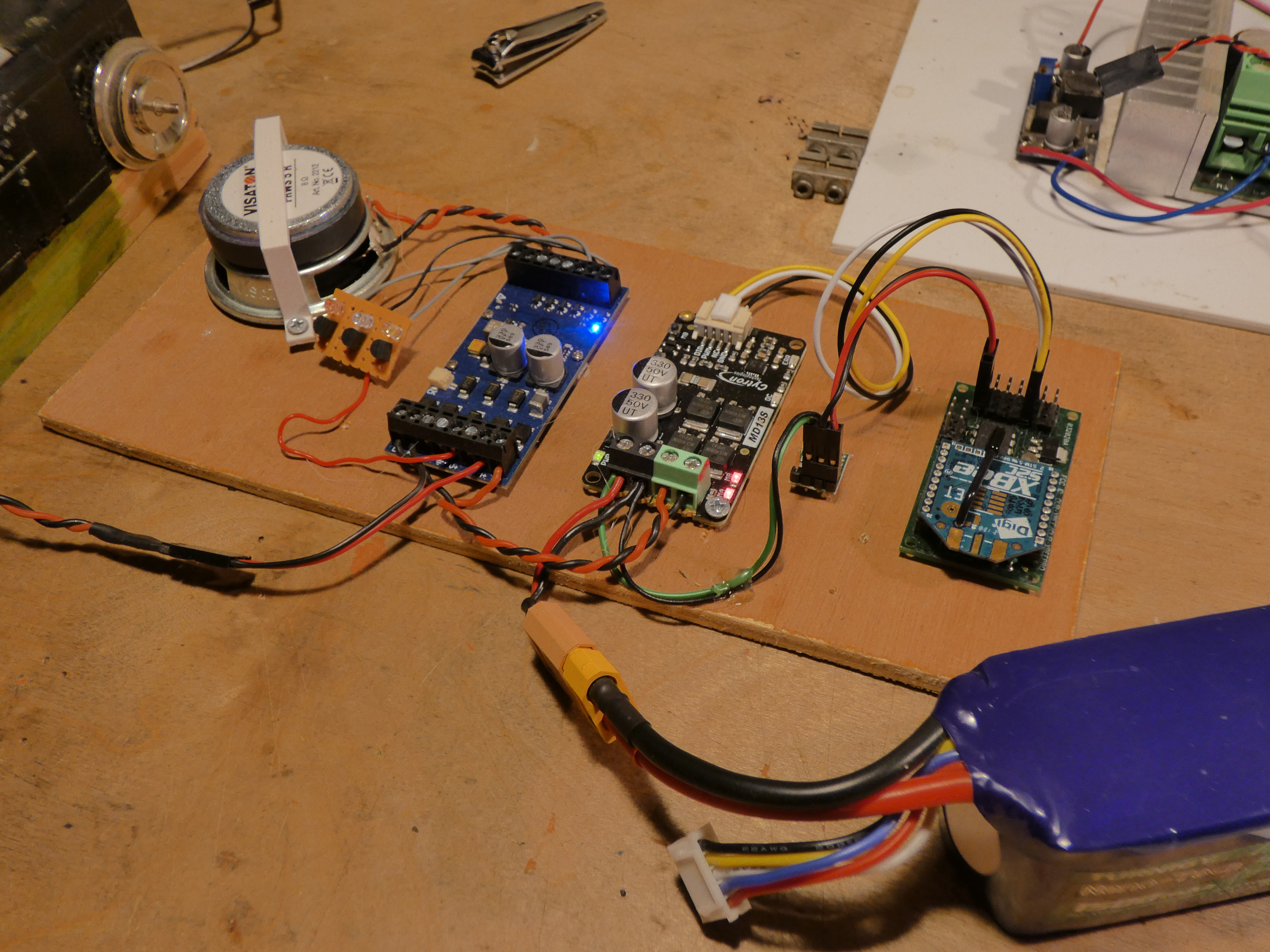
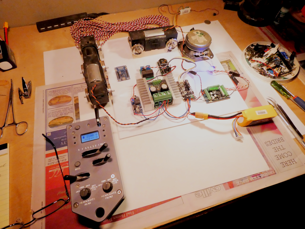
Sample Test Rig
Since these installations generally go into larger scale locomotives, it’s always best to get everything set up on the bench for some extensive testing before an install. Below is a pic of a test layout of both the Syren50 and the ESU Lok Sound 5A DCC decoder. The decoder is driving the lights and sound, as well as one of the power trucks. The Syren50 is hooked up to the 3 axle truck.
Connectors Description
Below is a diagram of the pins on the Receiver. These are standard R/C connections, the pins closest to the edge of the board are ground, the pins in the middle are +5v and the pins nearest the chip are the signal pins.
   Z   X   D   2   1   0   P
   |   |   |   |   |   |   |________ Power Connection (+5v)
   |   |   |   |   |   |____________ Servo 0 (Throttle)
   |   |   |   |   |________________ Servo 1 (Direction in steam mode)
   |   |   |   |____________________ Servo 2
   |   |   |________________________ Logic Level DCC signal
   |   |____________________________ Digital Output X
   |________________________________ Digital Output Z
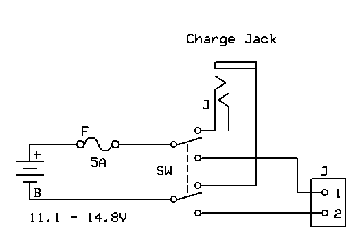
Power Connections
The schematic below shows how I wire all my installations. A DPDT switch is used to connect the battery to either the charge jack or power the system. This makes a nice clean break of all power to the system. DO NOT forget a fuse! If you use Lipo batteries, they can dump a TON of current if they are shorted and with no fuse it will melt wires and cause all sorts of havoc if you make a mistake and short them.